





What Is Micro Machining and How Does It Work?

Micro machining is the controlled production of extremely small features, often measured in micrometres. It serves medical devices, electronics, aerospace components, optical systems, and miniature sensors. Professor T. Masuzawa, a leading micromachining researcher, stated, “Micromachining is not merely conventional machining at a smaller scale.” That distinction matters. Smaller dimensions create different physical problems.

A cutting tool may be only a fraction of a millimetre wide. Tool runout then becomes a serious concern. A tiny error can distort a hole, edge, or channel. Engineers manage these risks through precision spindles, rigid machines, suitable cutting fluids, and carefully selected materials. Common processes include micro milling, micro drilling, micro turning, laser machining, and electrical discharge machining. Each method changes the workpiece differently. Heat, vibration, burr formation, and tool wear must be monitored closely.

The process usually begins with a detailed digital model. The machine then follows programmed toolpaths under controlled conditions. Operators check dimensions with microscopes, optical systems, or specialised measuring equipment. This is where theory meets experience. A perfect simulation does not guarantee a perfect part. Surface damage can appear unexpectedly. Small tools can fail without obvious warning.

That uncertainty deserves attention.

The purpose of this guide is to explain what micro machining is, how it works, and why accuracy depends on more than machine size. It will examine tools, materials, operating steps, advantages, limitations, and practical quality controls. Some applications seem straightforward. They are not always. Careful inspection remains essential.
What Is Micro Machining and How Does It Work?

What Micro Machining Means and Why It Matters

Micro machining means shaping extremely small features with controlled cutting, drilling, or material removal. It matters when ordinary tools cannot produce the required accuracy.

A groove thinner than a human hair can guide fluid, light, or electrical signals. At this scale, surface quality often affects performance as much as dimensional accuracy. Small errors become large problems.

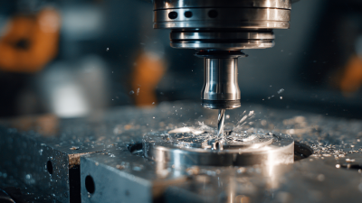
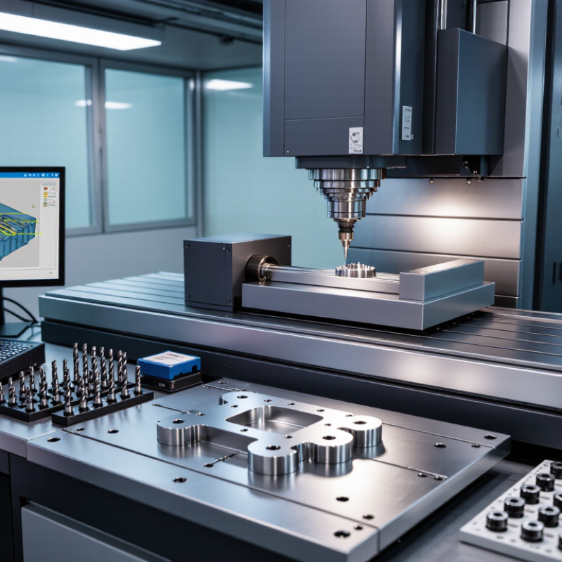
The process usually begins with a precise digital design and a carefully selected tool. A cutting tool may rotate at high speed while removing tiny amounts of material. Operators control feed rate, vibration, temperature, and tool wear.

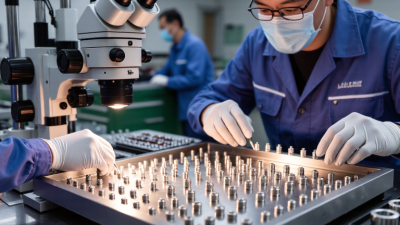
In practice, a clean working area is essential because one small particle can damage a delicate feature. Measurement is continuous, not an afterthought. Optical systems and high-resolution probes help verify edges, holes, and surface textures.

Micro machining supports medical components, miniature sensors, aerospace parts, and small fluid channels. Yet it is not simply normal machining made smaller.

Heat can distort the workpiece, while fragile tools may break without warning. It is tempting to trust the machine settings. That assumption can fail.

Reliable production needs experienced technicians, validated procedures, and repeated inspection. Even then, material behavior may differ between batches.

The difficult part is often knowing when the result is precise enough for real use.

The Main Principles Behind Micro Machining

What Is Micro Machining and How Does It Work?

The Main Principles Behind Micro Machining

Micro machining removes material with tools commonly smaller than 1 millimeter. The process depends on controlled cutting, not simply reduced-size conventional machining. A sharp tool creates a tiny chip while the spindle maintains high rotational accuracy. Feed rate, cutting depth, and tool edge radius must work together. A small error can damage the entire feature.

The 2024 Global Micro-Machining Market Outlook estimates annual industry growth near 8% through 2030. That growth reflects demand for miniature medical, optical, and electronic components. However, market expansion does not remove the physical limits. At microscale, the tool edge may approach the chip thickness. Instead of cutting cleanly, it can rub, bend, or fracture the material. This is where practical experience matters.

Heat control is another central principle. A tiny tool has little space to release heat, so excessive speed can soften materials or shorten tool life. High-pressure coolant, air flow, or carefully timed pauses may help. Metrology reports from national manufacturing laboratories emphasize measurement uncertainty below 10 micrometers for many precision features. That target is demanding. Surface inspection, tool runout checks, and in-process measurement are essential.

The process is not perfectly predictable. Material grain direction can change the cutting result. Tool wear may appear earlier than expected. Engineers often adjust parameters after examining real chips and surface marks. That feedback is imperfect, but it remains one of the most reliable parts of micro machining.

What Is Micro Machining and How Does It Work? - The Main Principles Behind Micro Machining

Dimension Key Information Typical Values or Examples
Definition Micro machining is the manufacturing of miniature components or features using controlled material-removal processes. Micro holes, slots, channels, gears, molds, medical components, and miniature mechanical parts.
Feature Size The process is used when critical dimensions or surface features are in the micrometer range. Features commonly range from several micrometers to a few hundred micrometers, depending on the process and material.
Basic Working Principle A precisely controlled tool, beam, electrical discharge, chemical reaction, or abrasive action removes a very small amount of material. Material is removed layer by layer or point by point according to a digital tool path or programmed pattern.
Mechanical Micro Machining Miniature cutting tools remove material through controlled contact between the tool and workpiece. Micro milling, micro drilling, micro turning, and micro grinding.
Laser Micro Machining A focused laser beam melts, vaporizes, or ablates material without direct mechanical contact. Suitable for fine holes, grooves, markings, and features in metals, ceramics, polymers, and thin films.
Electrical Discharge Machining Controlled electrical sparks melt and remove small volumes of electrically conductive material. Micro-EDM is used for high-precision holes, cavities, and narrow slots in hard conductive materials.
Electrochemical Machining Anodic material is dissolved by an electrochemical reaction, with the tool acting as the cathode. Useful for conductive materials and complex shapes where low mechanical cutting forces are important.
Chemical and Photochemical Machining Selected areas are protected with a mask while exposed material is chemically etched away. Commonly used for thin sheets, microchannels, screens, shims, and batch production of flat parts.
Suitable Materials Material selection depends on electrical conductivity, hardness, thermal behavior, chemical resistance, and process compatibility. Stainless steel, aluminum, titanium, nickel alloys, silicon, glass, ceramics, polymers, and composites.
Dimensional Accuracy Accuracy depends on machine resolution, tool condition, thermal stability, workholding, calibration, and process parameters. Specialized processes can achieve sub-micrometer positioning and micrometer-level feature control, but actual results vary by application.
Surface Finish Surface quality is influenced by tool geometry, cutting conditions, discharge energy, pulse duration, beam settings, and post-processing. Fine finishing operations can produce surfaces with roughness in the sub-micrometer to low-micrometer range.
Main Process Variables The operator controls parameters that determine removal rate, accuracy, heat generation, tool wear, and surface integrity. Feed rate, spindle speed, depth of cut, tool diameter, pulse energy, pulse duration, voltage, current, beam power, and etchant concentration.
Tool and Machine Requirements Micro machining requires high stiffness, low vibration, precise motion control, accurate fixturing, and reliable process monitoring. High-speed spindles, precision stages, optical inspection, fine-pitch drives, vibration isolation, and temperature control.
Tool Wear and Breakage Small tools have limited strength and can wear or break quickly because of their small cross-sectional area. Tool inspection, conservative cutting conditions, proper cooling, and compensation strategies are often required.
Heat-Affected Zone Thermal processes can produce localized melting, resolidification, residual stress, or a heat-affected zone. Lower pulse energy, shorter interaction times, optimized beam focus, and finishing passes can reduce thermal effects.
Inspection and Measurement Dimensional verification is essential because visual inspection alone cannot reliably assess micro-scale features. Optical microscopes, vision systems, laser measurement, profilometers, and scanning electron microscopy.
Advantages Micro machining enables small, precise, and complex features that conventional machining may not produce efficiently. High feature density, precise geometries, low material consumption, and compatibility with miniature products.
Limitations The process is sensitive to vibration, contamination, thermal drift, tool wear, workholding errors, and measurement uncertainty. Lower material-removal rates, higher setup demands, specialized equipment, and greater inspection requirements.
Typical Applications Micro machining is used where compact size, precise geometry, and controlled surface characteristics are required. Medical devices, microfluidic components, sensors, optical parts, aerospace components, miniature molds, and electronic assemblies.

Note: Actual feature size, tolerance, surface roughness, productivity, and material suitability depend on the selected process, machine configuration, workpiece material, tooling, and operating parameters.

Tools, Materials, and Equipment Used in the Process

Micro machining creates features smaller than one millimetre, often with tolerances measured in micrometres. The process demands sharp tools, rigid equipment, and careful measurement. Micro end mills may use carbide or diamond coatings. Their tiny cutting edges can break from heat, vibration, or excessive feed. Wire and sinker electrical discharge machining use controlled sparks instead of direct cutting. Ultrafast lasers can shape hard materials, though heat-affected edges still require inspection.

Material choice changes the entire setup. Stainless steel resists corrosion but generates difficult chips. Titanium is strong and heat-sensitive. Ceramics resist wear, yet they can fracture without stable support. Polymers need lower cutting forces and controlled temperatures.

Operators commonly use high-speed spindles, vibration-damping fixtures, precision linear stages, filtered coolant, and optical microscopes. Coordinate measuring machines then verify holes, slots, and surface profiles. The details are small.

The International Federation of Robotics reported 553,052 industrial robots installed worldwide in 2022. That figure shows how automation is expanding around precision production, including tool handling and inspection. However, robot motion alone cannot guarantee micro-scale accuracy. A 2023 measurement-science roadmap from the National Institute of Standards and Technology stresses traceability and uncertainty control in advanced manufacturing. In practice, temperature drift, tool wear, and dust may change a result within minutes. Engineers should record spindle load, cutting time, and inspection conditions. Even experienced teams sometimes trust a clean image too quickly. That mistake deserves more attention.

How a Micro Machining Operation Works Step by Step

Micro machining begins with a drawing, but the real work starts during process planning. Engineers define features measured in micrometers, select a suitable material, and inspect its hardness. A 2024 industry outlook projects roughly 8% annual growth for micro machining through 2030, reflecting demand for smaller medical, optical, and electronic components.

The machine then receives a highly detailed toolpath. A tiny carbide or diamond tool enters the workpiece at controlled speed and feed. Coolant removes heat, while vibration sensors monitor the cut. The operator checks tool wear after each short pass. A 5-micrometer error can ruin a narrow channel. That is not theoretical.

In practice, the operation is rarely perfectly linear. The workpiece is clamped, aligned, and measured before cutting. A roughing pass removes most material without forcing the tool. Finishing passes create the final wall and surface. After machining, an optical microscope or coordinate measuring system checks dimensions, burrs, and surface roughness. Measurement reports often target sub-10-micrometer uncertainty for critical features, according to precision-manufacturing guidance published by national measurement laboratories. Temperature still matters; a warm fixture can shift the result. I have seen excellent toolpaths fail because inspection began too late. The process improves when operators compare cutting data with actual measurements, then adjust cautiously. Overcorrection can create another error.

Applications, Benefits, and Technical Limitations of Micro Machining

Micro machining creates tiny features, often below one millimetre, through controlled cutting, milling, drilling, or electrical processes. Its value is clearest in medical components, miniature sensors, aerospace parts, and semiconductor tooling. A 2024 industry market report estimates that the global micro-machining sector could grow at roughly 8% annually through 2030. That growth reflects demand for smaller devices, not simply better machines.

The benefits are precise channels, lighter components, and reduced material use. Modern systems can hold tolerances near ±1–10 micrometres, depending on material, tool size, and process stability. However, scale creates difficult limits. A 0.2-millimetre tool can deflect, overheat, or break during a deep cut. Burrs may become larger than the intended feature. Surface inspection also becomes harder, especially inside narrow cavities. Industry process studies report that tool wear and heat remain major causes of dimensional drift. The numbers look impressive. Real production is less perfect.

Tips: Use short cutting paths, stable fixturing, and frequent tool checks. Measure the first part under controlled temperature. Do not trust simulation alone. Material grain, vibration, and coolant flow can change the result. A practical trial run may reveal limits that a technical drawing hides.